Archive

Posts Tagged ‘do it yourself’

Do It Yourself Kite Making

November 9th, 2010 1 comment

Last week I was inspired by a few consecutive windy days to go and fly a kite.  Unfortunately, I could not find one at the local stores, so I decided to make one myself.

My first attempt at a homemade kite was entirely self-guided and turned out less than stellar:

November 032

[Mikayla was not impressed.  Note: The power lines in the background were
never a worry since the kite never made it more than 4′ off the ground.
]

From this try I learned a few things:

  • It is worthwhile to learn from other’s instruction.
  • Good wind does not make up for bad design.
  • Tails on poorly made kites do help… but not enough to matter.
  • The convex side of the kite should face you not the concave side (a kite is not supposed to “grab” the wind, it is suppose to skip off it.)

I swallowed my pride and did some research on the internet on basic kite design.  The most helpful site I found was My Best Kite.  My second attempt at a kite followed the basic instructions for the large diamond dowel kite.  After that attempt proved to be a success, even in light wind, I made a few adjustment and built Kite #3.  Here is how I did it:

Step #1 – Get your plastic

I started with a large strip of black plastic sheeting I had laying around, but you could easily use a large garbage bag and get the same results.  I cut it to roughly 38″ x 38″ to work with the 36″ x 3/16″ dowels I got at my local superstore.

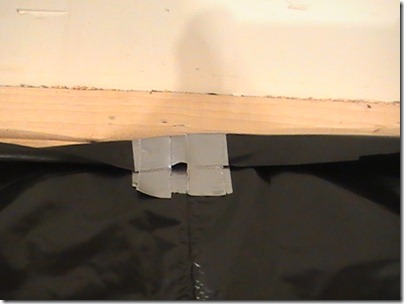
Step #2 – Create your vertical pocket

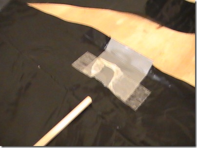
I used duck tape just for durability.  I am sure a lighter tape would work fine too, but I have had no problems with the great grey miracle.  All I did was take a 4″ section and double it over the top center of the plastic (I had a nice crease that made things easier to line up).  I then folded that down and used two smaller strips to secure it in place.

PIC_0078

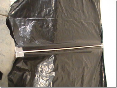
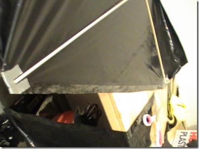
I then put the dowel rod (technically called a “spar”) in the top pocket and then moved to the bottom. I trimmed the plastic to make it the right height, then created a matching pocket that allowed the dowel to pull tight, but not enough to bow it.

PIC_0081

Step #3 – Prep the Horizontal Spar

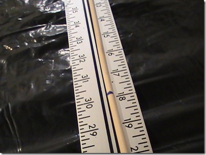
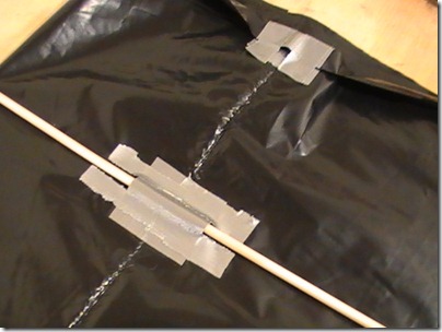
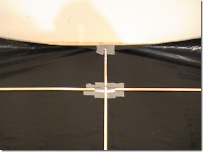
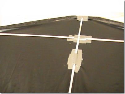
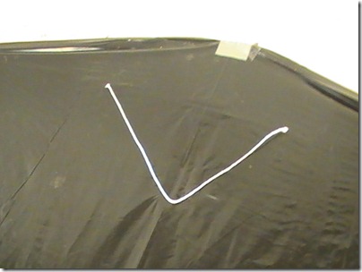
Find the center of your horizontal spar and mark it.  Then mark your vertical spar 6″ down from the top.  These will form the support for your kite.  There are several ways you can affix them together.  You can attach a tie point (as seen on the website) , you can simply tape them together (that is what I did for Kite #2 and it worked fine) or you can create tunnel pockets on the kite.  For this design I tried the later.

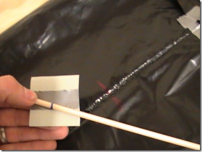
To do it, simply cut a 2-3″ inch strip of duck tape, flip it over, then attach a smaller strip down the middle.  Place that at the 6″ point for the horizontal spar.  Use additional tape if you so desire.

PIC_0083

PIC_0088

PIC_0090

After completing the kite, I decided use a vertical tunnel pocket as well and installed it after the fact a few inches below the horizontal pocket.  It would certainly make sense to do that at this stage as well.  You can see a picture of it down in Step #5

[NOTE: See Update below for tips on improving this process.]

Step #4 – Create the horizontal pockets and bow mechanism

In order for a kite to be stable while it flies, it needs to deflect the wind.  The easiest way to do this is to create a bow in the kite.  For Kite #2 I followed the instructions on the internet and used notches and a toggle.  It worked fine, but took a good bit of time to get right and was not adjustable.  For attempt #3, I decided to try another approach and use a bow line attached to the corner pockets.  I am sure there are multiple ways of doing this but here is a method that worked for me.

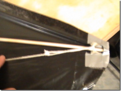
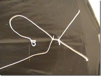
Begin by laying out your horizontal pockets just like you did the vertical ones by cutting the plastic so you have a small over lap and doubling up duck tape.  Go ahead and crease it so you know where they will be when they are complete.  Again, you want the spar to be tight, but not already flexing.  Then install a tie off point.  I used some fiber tape that was folded up in the middle.  Then you can secure the pocket like normal.  [Note: You want to keep the loop a bit large so you can slip the spar in under it into the pocket.]
PIC_0093

PIC_0095 [Sorry for the blurry pictures, but I think you get the point.]

Step #5 – Secure the Edges

At this point your kite should be coming together.  Go ahead and install both spars.  You should be seeing lines of tension in the shape of a diamond.

The internet instructions have you cut out the kite design first, but I have found it is much easier to make your cuts at this stage of the build.  This way your kite is cut exactly along your points of tension instead of loosely fitting your design.

PIC_0094

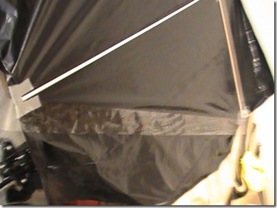
To secure the edges take a long strip of clear packing tape and affix it from spar pocket to spar pocket.  You will want the tape to run right next to the end of the spars.  You can simply tape over the folded plastic.  Once this is done, all you need to do is cut along the center of the tape.  Do this for all four edges.

PIC_0096

PIC_0097

PIC_0099

Step #6 – Attach your Bow Line

We are now ready to give our kite some shape.  Cut a long piece of cotton twine about 45″.  Thread each end through the tab you created on the corner pocket and tie it with a prusik knot.  This will be your bow line.

A Quick Note about Knots

Knowing various knots sure can help the kite making process.  If you are not familiar with ropes and knots, this may be a bit difficult.  I have found many of the techniques used here can be side stepped with some creative thinking.  For instance, in many cases you can simply tie loops in in your line and attach things together with a paper clip or a fishing snap.  For this whole project I used prusik knots because they are relatively easy, secure and adjustable.  Prusiks are generally tied using a loop of cord that is wrapped through itself (see example here).  If you wish, you can make a prusik from a small loop then tie the end of your cord to the “tail loop.”  However, you can also tie a prusik from a single line and then secure it with a half hitch.  That is what I have done for my kite.  I have recorded a video on how to tie a prusik knot on the end of a line.

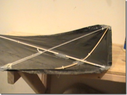
The prussic knot will allow you to adjust the tension on the bow line because as a friction knot, you can slide it into place and it will remain there.  Ideally, you want your horizontal spar to bow about 3″ (that is the distance from deepest part of the spar to the bow line.)

PIC_0106

PIC_0107

Step #7 – Attach the Bridle

From the center of your kite measure 6″ in both directions and mark it on your horizontal spar.  Cut a small hole in the plastic so you can thread some line through.  Cut about 20-24″ of line and thread it through bottom of your kite.  Secure line with several knots (and perhaps a bit of wood glue like I did).  When this line is finished, you should be able to pull it away from the body of the kite and it be about 6″ to the apex.  Adjust your knots and line if you need to.

PIC_0102

Measure up 12″ from the bottom of you kite and cut a similar hole.  Attach a 36″ piece of line to the vertical spar.  These three points will form the bridle of your kite.

Now here is where I got fancy.  Instead of just tying the lines together to form a three-line bridle, I decided to incorporate prusik knots into the design so I could adjust things on the fly.  Using a short bit of line, I tied a prusik to the horizontal line and then tied another prusik to the vertical line.  This allowed me shift the focal point of the bridle side to side and forward and back.  This gave me plenty of opportunity to experiment with optimal flying configuration and to adjust for inconsistencies in weight and/or balance.

If you don’t want to get fancy, just tie thing together so the apex of the pyramid from your lines is directly over the horizontal spar (perhaps an inch forward if you want) and about 6″ off the kite body.  Remember to include a way to attach your line.  For my design, I simply added a loop to the end of the long vertical line.

PIC_0105

Step #8 – Give it a test flight

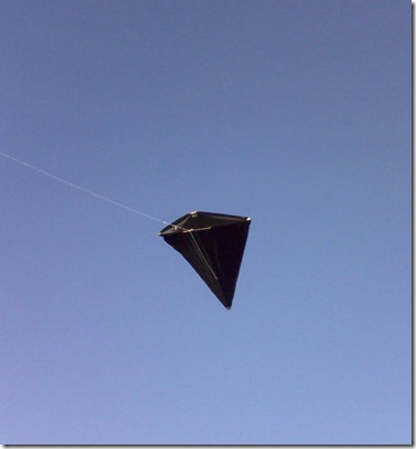
At this point, your kite should be complete.  Be careful not to over-tighten the bow line or your spar will break (a fact I have already learned from experience – luckily I was able to replace it in just a few minutes).  I used 17# test fishing line to fly the kite and had no problems at all.  I was able to get it to a height of over 450′ in only a slight breeze.

1109101552-01

[Home made kite in action.]

Overall this design is relatively straight forward and allows for variations and minor flaws.  It does not require much wind and is easy to modify if needed.  It is also very cheap and can be completed in less than an hour.  I l look forward to tweaking things a bit more to see what I can come up with.

UPDATE:

I recently made these kites with some friends and I figured out a little trick.  Rather than doing a single tunnel pocket for the horizontal spar, I did two offset by 6″ from center.  This not only provided more stability and made it easier to see the center marks, but it also allowed me to tie the harness around the tunnel pocket instead of around the spar itself.  This means if you ever break a spar, it is easier to replace because you just slide it out and the harness remains.  I also added a second tunnel pocket 12″ up from the bottom the vertical spar and used this as an attach point for the harness.

I also modified the tensioner for the bow (horizontal) spar.  Instead of only taping to the inside, I wrapped the packing tape all the way around the corner for a more secure hold.  I also used a single large loop between the tie offs and used a single prusik knot with a tail.  This maintains the balance, and only requires a single adjustment.

Work Around the Garage

March 30th, 2010 No comments

2010-03-30 Spring has sprung 045

I wouldn’t consider myself to be especially handy.  I can change my own oil, and know how to run a few power tools.  But, these are not indications of how handy I am, but rather point out just how cheap I am.  I refuse to take my car to the shop if it something I think I can figure out on my own (and after 10+ hours, with plenty of busted knuckles, I either get it figured out, or I have screwed it up so bad that I have no choice but to take it in).

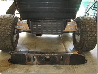
Case in point: I broke the steering arm on my riding lawn mower, which effectively meant my wheels were falling off and I could only change directions by kicking the tires while they were moving.  Did I take it to the shop to get fixed?  No.  Did I get someone to weld me a new support arm? No.  Instead, I decided to fashion a replacement out a 2×4, metal brackets, cut washers and .some furniture sliders.

2010-03-30 Spring has sprung 032

After a few adjustment, it works like a charm.  Now lets just see if I can get it to last through the summer.

Suspended Shelving and Fold-down Workbench

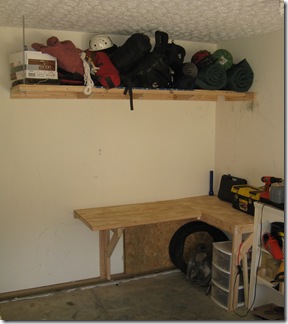
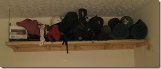
My most recent project has involved building some shelving and a work bench in the garage.  I needed to be able to get our outdoor gear out of the way, store my tools and have a workbench to complete projects on (the top of the deep freeze just wasn’t cutting it anymore.)

The first piece I completed was the suspended shelving.  I knew I wanted to build it out of plywood and 2x4s (for easy of construction and cost) and I did not want to have massive supports jutting out.  So I came up with a design that utilizes 2×4 cleats screwed to the studs and then a 3/8" threaded rod supporting one corner

2010-03-30 Spring has sprung 034

I started by marking the height I wanted the shelf and then screwing in two perpendicular 2x4s.  For my garage, it made sense to hang the shelf 48" from the ceiling.  [NOTE: I should have attached the shorter cleat first to maximize the number of studs it could screw in to.]

I then constructed the shelf itself.  I screwed 2x4s along two sides of 1/4" (2′ x 8′) plywood.  [NOTE: Be sure to leave room for the cleats you previously installed.  I forgot to do this on the short side and had to notch the cleat.]  With someone’s help, hoist the shelf up onto the cleats.  One or two strategic screws should hold it in place while you complete the project.  I waited to install the final screws until I had the rod installed to help support the weight.

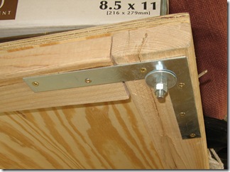
Next I installed a 90 degree bracket to help hold things together and to spread the weight distribution.  By drilling a hole through the apex and using a large washer, I was able to provide a good support for the connecting rod.

2010-03-30 Spring has sprung 043

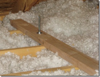
I passed the threaded rod through this support and secured it with a large washer and two bolts.  I left roughly six inches below the bolts in case I needed to adjust things.  The rod then passed through the drywall in the ceiling where it was secured to a 2×4 passing over multiple joists.

2010-03-30 Spring has sprung 042

Besides being less obtrusive, the main advantage to using a threaded rod to support the shelf is that you can adjust it after installation.  Once the rod was secured on both ends, I was able to use the bolts to ensure everything was perfectly level.  I then cut off the excess bolt.

The only thing remaining to complete the project was to include supports.  I added 3 by tapering a 2×4 down to 1.5" and securing from the top.  These were then affixed to the cleat.  [NOTE: If I had planned ahead, I could have attached these to the cleat before I installed it and it would have resulted in a much more stable design.]

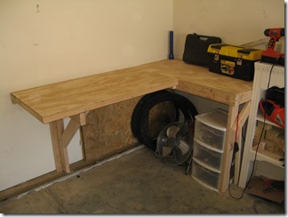
Once I had the suspended shelving complete (and the resulting clutter out of the way), I could turn my attention to building a work bench.  One thing I had to consider was the depth of my garage.  Because things can get cramped, I wanted to be able to have get the workbench out of the way if I needed to.  I decided on a two part design with a permanent section and a folding section.  I built the surface out of the other half of the plywood from the shelving project.

2010-03-30 Spring has sprung 033

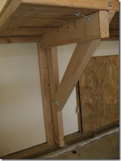
The permanent section was relatively straightforward.  I built a one-legged frame out of 2×4’s and then attached it to the studs in the wall.  I used brackets to attach the support to the leg.  I then screwed the work surface onto the frame (there is a center support to help distribute weight that is built into the frame).

The drop-down section took a bit more thinking.  I began by attaching a 2×4 cleat flush with the permanent section of the workbench.  Then, along the furthest-most stud, I attached a perpendicular 2×4 to anchor a hinged support.

I built the drop down section out of the remaining plywood with a 2×4 frame.  This time I did not use center supports because the whole section is not designed to support a lot of weight.

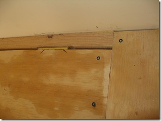
I used heavy duty door hinges to support the whole apparatus.  I notched the support cleat as well as the work surface so that it could remain flush with the other work bench. 

2010-03-30 Spring has sprung 049

The hardest part was trying to align the hinges when attaching the workbench to the wall.  To do this, I attached a 2×2 on the permanent section to help support things then held the fold away bench against the cleat while trying to get it level.  I had someone else go under the bench and mark where the bottom of the hinges were.  I then took a spare hinge and used it as a guide to pre-dill the holes.  From there it was relatively easy to screw the hinges into place. 

The hinges were strong enough to support the workbench temporarily, but I needed to build something more sturdy.  For that, I used the same style hinges and fashioned a simple support out of 2x4s that secured into place with a basic latch.

2010-03-30 Spring has sprung 038

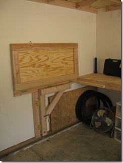
When not it use, the support and table top can fold flat against the wall.  I used another latch to secure it in the up position.

2010-03-30 Spring has sprung 039

The whole project took about $60 in materials and 10 hours in labor.  I probably could have done it much less time if my miter saw had been working and I had thought through my final design a bit more.

If I value my time at even minimum wage, I doubt I saved much.  But, just like with the home made diaper sprayer we installed, there is just something rewarding about completing a project on your own.

Do It Yourself Diaper Sprayer

March 16th, 2010 14 comments

Beth and I have been very pleased with our decision to use cloth diapers.  Besides the washing every couple days, the only thing that really requires more effort than disposables is the need to clean the #2 off of diapers.  You can splash them around in the toilet, but most people prefer to use a diaper sprayer.

You can purchase these from a variety of places (see here, here and here).  These generally run about $40.  However, if you are up for it, you can build your own homemade diaper sprayer for $25-30 in less than 30 minutes. Below you will find instructions and a parts list for the method I have used for two installs.

Before you begin, you need to know a bit about basic plumbing and various fittings.  There are several thread patterns used in household settings, a few of which come into play for this project.  Most toilet water lines have 3/8″ OD (outside diameter) compression fittings.  Your standard kitchen sprayer connects with 1/4″ FIP (Female Iron Pipe Thread).  Most toilet connections are either 1/2″ or 7/8″ MIP (Male Iron Pipe Thread).  The tricky part to hooking up a diaper sprayer is trying to get these thread patterns to work together with the fewest adaptors. [NOTE: You don’t need to remember all of this, but it is helpful to know when talking to an associate at a hardware store.]

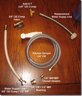
Parts

Here is a list of parts I used to complete the project along with their approximate prices:

  • Standard Kitchen Sprayer with 1/4″ FIP connection – $7
  • 1/4″ MIP Closed Adaptor (converts FIP to MIP) – $2
  • 1/4″ FIP > 1/2″ MIP reducer (also called a bushing) – $2
  • Standard water supply line – 3/8″ OD Compression > 1/2″ FIP (easiest and cheapest way I have found to convert standard thread to compression connections) – $4
  • Add-A-Tee 3/8″ OD Compression (Allows you to add a second supply line to your existing toilet valve without having to shut off the water main) – $6
  • Water Supply Valve (3/8″ OD Compression input and outlet.  This may be omitted) – $8
  • Replacement Water Supply Line (match to your current toilet configuration.  May be omitted if old supply line works with new setup) – $4
  • Teflon Tape (for non-compression fittings) – $1

Parts

Parts for the most basic set up should cost just a bit over $20.  I was able to pick up all these parts at my local Lowes (I generally prefer Home Depot, but found for plumbing accessories Lowes has a better selection). The final bill for the setup described here was roughly $32.

NOTE: If these parts are not available, you may have to improvise.  If that’s the case it very helpful to know the specific thread conversions you are trying to achieve (see details above).

Installation

  1. Begin by shutting off the toilet water valve, draining the toilet, and removing the old water supply line (keep this handy in case you can reuse it or for reference if you replace it).  You may want a bucket to catch any water draining from the tank.
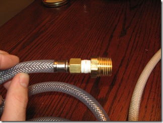
  2. Connect the adaptor and reducer (bushing) to the kitchen sprayer.  You will want to put Teflon tape around the threads to prevent leaks.
    2010-03-16 Tally 005
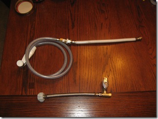
  3. Next connect the water supply line to the 1/2″ reducer you just installed.  Again, you will want to use Teflon tape for this one.
  4. Attach the 3/8″ compression valve to the Add-a-Tee adaptor as well as the water supply line you will be using for your toilet to the  (you shouldn’t need to use Teflon tape for this).
    2010-03-16 Tally 008
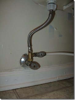
  5. At this point you should be able to connect everything else up.  Connect the sprayer assembly to the valve and then connect the whole apparatus to your toilet water valve and the toilet.

Your final setup should look something like this:

2010-03-16 Tally 009

Options

Depending on your setup, your access to plumbing supplies and your skill level, there are a few modifications you could try:

  • Omit the extra valve and simply use the main water supply valve to moderate pressure.  This is how we did the first set up.  It works well and saves quite a bit of money since the valve is by far the most expensive part.  Your options then are either a slow filling toilet or a super powerful sprayer.
  • Instead of messing with the closed adaptor, bushing & water supply line, you could cut off the old 1/4″ FIP connector and affix a compression fitting.
  • If you have easy access to the main water line, it may be easier to swap the valve out for one with two connectors.  Some valves have both compression and standard MIP connections.
  • You can use different fitting combinations to achieve the same result.  For instance, it may be cheaper to use a 1/2″ valve instead of a 3/8″ compression valve to moderate your water flow.  Likewise, you may be able to go straight from 1/4″ FIP to 3/8″ compression without using the extra fittings.

——

I am by no means a plumber, but I found the following procedure relatively simple and only needed an adjustable wrench to complete the project.  The hardest part was figuring out which thread patterns I had and which parts I would need.

After I had wrapped up the install and was writing this blog entry I came across a post which outlines a similar procedure.  Perhaps it will be helpful for you.  Doing this project yourself will not save you a whole lot of money (probably $10-15) but you will have the satisfaction knowing you can make your own diaper sprayer.